Mettler Sonicator Plus 994
|
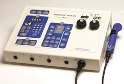
The microprocessor-controlled Sonicator Plus 994 is a four channel combination unit. It combines 1 and 3 MHz ultrasound with six treatment waveforms: Interferential, Premodulated, Medium Frequency, Biphasic, High Volt and Microcurrent. A dual frequency 5 cm2 applicator comes standard with the unit. Up to five different treatment protocols may be set-up simultaneously using different timers.
Weight: 10.7 pounds, (4.9 kg)
Dimensions: 5 in (H) x 14.5 in (D) x l0 in (L), (12.7cm (H) x 36.8 cm (W) x 25.4cm (L))
 
Warranty: 2 years on unit, 1 year on applicator and cable
1
Sonicator
® Plus 994 Specifications
General Specifications:
Input: 90–240 VAC, 50–60 Hz, 2.3 Amp. Nom.
Certification:
The Sonicator Plus 994 complies with the ultrasound
performance standards set forth in the Code of Federal
Regulations, Title 21 (Food and Drugs), Part 1050.10 and
IEC 601-2-5, 1
ETL and C-ETL Listed:
st Ed., 1984
Domestic model
Model ME 994 (9801427)
Classification: Protective Class I Equipment
CE model
Enclosed equipment without protection against ingress of
water.
Equipment not suitable for use in the presence of a
flammable anesthetic mixture with air or with nitrogen oxide
Year 2000 Compliant Yes
U.S. Patent Numbers: U.S. and foreign patents applied for and granted including
U.S. Patent Numbers 4,966,131 and 5,095,890.
Weight: 10.7 pounds
4,9 kg
Dimensions: 5 in (H) x 14.5 in (W) x 10 in (D)
12.7 cm (H) x 36.8 cm (W) x 25.4 cm (D)
Operating Temperature: +50°F to +104°F
+10°C to +40°C
Humidity: Operating, 30% to 75% Relative Humidity at 104
Nonoperating, 5 to 95% Relative Humidity, non-condensing
Storage Temperature: -40°F to 167°F
-40°C to 75°C
Storage Humidity: Storage, 30% to 90% Relative Humidity at 40º C, Noncondensing
Storage Pressure: 700-900 mB
Environmental Disposal: The device contains lead in the form of solder used to
produce electrical contact between components. To avoid
adverse environmental impact, utilize a disposal facility that
performs complete incineration of the device at a temperature
in excess of 1000°C.
The shipping materials are fabricated of cardboard and may
be disposed of with other paper products.
2
Treatment timer:
Timer Accuracy: ±0.5 minutes for times less than 5 minutes
±10% for times from 5 to 10 minutes
±1.0 minute for times greater that 10 minutes
±5%,
Type BF Equipment°F (40°C)CE specification
Maximum Treatment Time: 60 minutes–electrical stimulation
30 minutes–ultrasound or combination therapy
Treatment Timer: Treatment time counts down to zero when a time is set, or up
to 60 or 30 minutes when no time is set. The digital timer
indicates time in minutes and seconds. The timer also
indicates the remaining or elapsed treatment time during the
“Hold” period.
Ultrasonic Generator Specifications:
Frequency: 1.0 MHz ±5%
3.2 MHz ±5%
3.3 MHz ±5%
Modes: Continuous
Pulsed—20% duty cycle
Pulsed—50% duty cycle
Modulation: 100%
Modulation Waveform: Rectangular
Pulse Repetition Rate:
Modulation Frequency
100 Hz ±20%
Pulse Duration:
Modulation Period
2 msec ±20%, 20% duty cycle
5 msec ±20%, 50% duty cycle
Temporal Peak/ average
intensity ratio:
5:1 ±20%, 20% duty cycle
2:1 ±20%, 50% duty cycle
Maximum output power: 22 W with a 10 cm² applicator, (ME 7310)
11 W with a 5 cm² applicator, (ME 7513)
2.2 W with a 1 cm² applicator (ME 7331)
Maximum intensity: 2.2 W/cm² with all applicators
Indication accuracy: ±20% (for any level above 10% of maximum)
Output description: The output waveform is continuous or pulsed as programmed
by the membrane panel control. In the pulse mode the 1, 3.2
or 3.3 MHz square wave pulses
are modulated. The power level is adjusted by varying the
pulse amplitude. The pulse waveforms are shown
below:
3
Time
Output
1, 3.2 or 3.3 MHz
Ultrasound
Pulse Width
2 ms
Pulse Space
10 ms
Figure 3.1—Pulse Waveform—20% Duty Cycle
Time
Output
1, 3.2 or 3.3 MHz Ultrasound
Pulse Width
5 ms
10 ms
Pulse Space
Figure 3.2—Pulse Waveform—50% Duty Cycle
In the continuous mode, the power is on at least 95% of the
time the timer is running. The continuous mode waveform is
shown below:
Time
Output 1, 3.2 or 3.3 MHz Ultrasound
Figure 3.3—Continuous Waveform
Ultrasonic Applicator Specifications:
Piezoelectric discs: The output transducer utilizes a barium titanate disc with a
specially coated face.
Individual Applicator Specifications:
Applicator Part Number Frequency Effective Radiating Area
ME 7310 1 MHz ±5% 10 cm²±10%
ME 7331 3.3 MHz ±5% 1 cm² ±10%
ME 7513 1 or 3.2 MHz ±5% 5 cm² ±10%
Maximum Beam
Non–Uniformity Ratio:
6:1
Maximum Effective
Intensity Ratio:
2:1
Spatial Pattern: The applicator produces a collimated (cylindrical) beam with
an area of 1, 5 or 10 cm², measured 5 mm from the ceramic
disc surface when the radiation is emitted into the equivalent
of an infinite medium of distilled water at 30° C.
The beam of the applicator is circular in all planes parallel to
4
the applicator face. A few inches from the face, it is a single
smooth bell-shaped curve. Nearer the face the pattern varies
more due to phase cancellations. Sample curves measured in
the far field from the surface are shown in Figures 3.3, 3.4,
3.5 and 3.6.
Figure 3.4—10 cm² Applicator (1 MHz), ME 7310,—Three Dimensional Beam Pattern
Figure 3.5—5 cm² Applicator (1 MHz), ME 7513—Three Dimensional Beam Pattern
Figure 3.6—5 cm² Applicator (3.2 MHz), ME 7513—Three Dimensional Beam Pattern
Figure 3.7—1 cm² Applicator (3.3 MHz), ME 7331—Three Dimensional Beam Pattern
5
Waveform Specifications:
Interferential Mode
Figure 3.8—
Interferential Waveform
Waveform Type: Sinewave
Polarity: None
Volts: 0–65 volts RMS, 1 Kohm load
Current: 0–65 mA RMS, 1 Kohm load
Average current at
maximum intensity
and frequency: 65 mA RMS
Maximum current
density under 2"
diameter electrode. 3.2 mA/cm²
Frequency: Channel 1 = 4000 Hz
Channel 2 = 4000 to 4250
Hz variable frequency sine wave
Frequency Modulation: 1–15 Hz
80–150 Hz
1–150 Hz
xx–xx Hz,
xx=any value from
1 to 250 Hz
Phase Duration: 125
Available Amplitude
Modulation Options: Vector rotation
Available Channels: Channel pairs 1 & 2 or 3 &4
μs
Premodulated Mode
Figure 3.9—Premodulated
Waveform
Waveform Type: Amplitude modulated
sine wave
Polarity: None
Volts: 0–50 volts RMS, 1 Kohm load
Current: 0–50 mA RMS, 1 Kohm load
Average current at
maximum intensity
and frequency: 50 mA RMS
Maximum current
density under
2" diameter electrode: 2.5 mA/cm²
Frequency: 4,000 Hz
Frequency Modulation: 1–15 Hz
80–150 Hz
1–150 Hz
xx–xx Hz,
xx=any value from
1 to 250 Hz
Phase Duration: 125
6
4–1,000 ms beat envelope
Available Amplitude
Modulation Options: Continuous
Surge
Reciprocation
Available Channels: All
μs internal sine wave
Medium Frequency Mode
Figure 3.10—Medium
Frequency (
Waveform
Waveform Type: Burst modulated sine wave
Polarity: None
Volts: 0–50 volts RMS, 1 Kohm load
Current: 0–50 mA RMS, 1 Kohm load
Average current at
maximum intensity
and frequency: 50 mA RMS
Maximum current
density under 2"
diameter electrode. 2.5 mA/cm²
Frequency: 2500 Hz, Burst at
10 ms on and 10 ms off
Frequency Modulation: No
Phase Duration: 200
Available Amplitude
Modulation Options: Continuous
Surge
Reciprocation
Available Channels: All
Russian)μs
Biphasic
(TNS) Mode
Figure 3.11—Biphasic
(TNS)
Waveform
Waveform Type: Symmetrical biphasic square
wave
Polarity: None
Volts: 99 volts peak, 1 Kohm load
Current: 0 –99 mA peak,
1 Kohm load
Average current at
maximum intensity
and frequency: 7.2 mA
Maximum current
density under 2"
diameter electrode. 0.36 mA/cm²
Frequency: 1–120 HzzHz
Frequency Modulation: No
7
Phase Duration: 50–300
Available Amplitude
Modulation Options: Continuous
Surge
Reciprocation
Available Channels: All
μs
High Volt Mode
75 us
0 volts
500 volts
50 %
8 us
Figure 3.12—High Volt
Waveform
Waveform Type: Monophasic twin peak
Polarity: Positive or negative
Volts: 500 volts peak, 1 Kohm load
Current: 0–500 mA peak, 1 Kohm load
Average current at
maximum intensity
and frequency: 1.2 mA at 120 pps with
1 Kohm load
Maximum current
density under 2"
diameter electrode. 0.06 mA/cm²
Frequency: 1–120 HzzHz
Frequency Modulation: No
Phase Duration: 8
Polarity: Positive or negative
Available Amplitude
Modulation Options: Continuous
Surge
Available Channels: Channel One only
μs at 50% Vmax
Microcurrent Mode
+
-
or
+
-
Figure 3.13—Microcurrent
Waveform
Waveform Type: Monophasic or biphasic
square wave
Polarity: Positive or negative or
biphasic pulses
Volts: 1 Volt peak, 1 Kohm load
Current: 10-990
Average current at
maximum intensity
and frequency: 990
Maximum current
density under 2"
diameter electrode. 24.4
Frequency: 0.5-500 Hz
Duty Cycle: 50%zHz
Frequency Modulation: No
Pulse Duration: 1-1000 ms
8
Available Amplitude
Modulation Options: Continuous
Available Channels: Channel Two only
μA peak, 1 Kohm loadμAμA/cm²
Amplitude Modulation Specifications:
Vector rotation:
Interferential Mode Only
-50% amplitude modulation in
anti phase with an eight second modulation period.
Surge Mode:
Premodulated, Medium Frequency and Biphasic (TNS) Pulsed Modes
Up ramp: 3 seconds
Down ramp: 2 seconds
Preset on/off times: 10 seconds on, 10 seconds off
10 seconds on, 20 seconds off
10 seconds on, 30 seconds off
10 seconds on, 40 seconds off
10 seconds on, 50 seconds off
10 seconds on, 60 seconds off
Programmable On time: 1–240 seconds
Programmable Off time: 1–240 seconds
Reciprocation mode:
Premodulated, Medium Frequency and Biphasic (TNS) Pulsed Modes
Up and down ramps: 1 second,
reciprocation only
Reciprocation time: 2–240 seconds, (On time = off time)
Combine with Surge: Use up and down ramps of surge program
Use on/off times of surge program.
Two timer option: No
|